SPZ-500 Automatic Flight Control System
System Description
The MU-2 Marquise incorporates the SPZ-500 Automatic Flight Control System (AFCS), originally developed by Sperry Corp. The SPZ-500 AFCS integrates an autopilot, a flight director computer and air data computer (ADC) to provide a full complement of horizontal and vertical flight guidance modes.
The SPZ-500 autopilot can be operated in two broad modes. The first broad mode is coupled mode, as in coupled to the flight director computer (FD computer) and the other broad mode is uncoupled from the FD computer. When operating in the coupled mode, the autopilot will receive its pitch and roll commands from the FD computer, which is controlled via the mode control panel (MCP) mounted on the top of the glareshield and one or more of the AP mode buttons (except the SBY button) will be illuminated on the MCP. When operating in uncoupled mode, the autopilot takes its pitch and roll commands from from the pitch and roll control inputs set via the autopilot controller panel between the seats and only the SBY annunciator on the MCP will be illuminated. A combination of coupled and uncoupled modes is also possible. For example, pitch control could be via the pitch wheel on the autopilot controller, while roll control, say in HDG mode is via the flight director.
The SPZ-500 autopilot servo motors may be disengaged while the FD computer is still operating. This means that the MCP on the glareshield can have mode buttons illuminated, but the aircraft will not respond to the flight director cues on the instruments. This is typical when hand flying the FD cues as may be common after takeoff. You can read more about this method in the procedures for takeoff and climbout
The autopilot is engaged by pressing the AP ENGAGE button on the controller between the seats. Pressing the ENGAGE button will automatically turn on the yaw damper also; however, the yaw damper may be operated independently of the autopilot. The autopilot will not engage if the TURN knob on the controller is not centered. Pressing the AP ENGAGE button when the autopilot is already engaged will NOT turn off the autopilot. The autopilot is normally disconnected via the red AP disconnect button on the pilot's yoke; however, the following events will also disconnect the autopilot:
-
Actuating the electric pitch trim
-
Pressing the go-around button
-
turning the LH radio master switch OFF
-
Pulling the Autopilot DC fuse (behind pilots left shoulder)
-
Turning the Master switch to ON
-
(TODO) Actuating fast erect switch (Steam Gauge only)
-
(TODO) Actuating compass INC-DEC switch (Steam Gauge only)
The SPZ-500 also incorporates TCS, or Touch Control Steering. The TCS system allows the pilot to set pitch, roll, ALT, VS and IAS targets by manually flying the aircraft to those target values, rather than setting target values via separate devices, which can take up panel space. TCS is activated via the black button on the pilot yoke. When TCS is active (button held down), then the autopilot servos are temporarily disconnected and target values of active modes are updated constantly as long as the TCS button is held down. When the button is released, then the AP servos are re-engaged and the instant values of active modes at the time of button release become the new target values to hold.
SPZ-500 Controls and Instruments
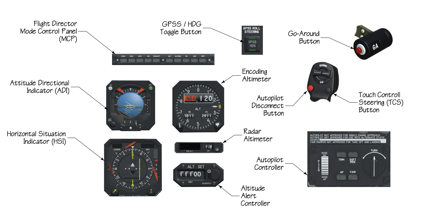
The OEM (Original Equipment Manufacturer) components of the AFCS that are accessible by the pilot and used to interface with the AFCS are shown below. The following descriptions will only relate to those instrument functions that have applicability to the autopilot. Other integrated functionalities of the AFCS instruments that are not applicable to the autopilot are described elsewhere in the Instruments section.
NOTE: The G500 GLASS version of the MU-2 incorporates the ADI / HSI / Altimeter / Alt Alert Controller into its glass display.
In addition to the above cockpit components, the AFCS also is comprised of the following equipment installed in various locations around the aircraft.
- Flight Director Computer
- Autopilot Computer
- Air Data Computer
- Servo motors
- Remote Vertical Gyro for roll/pitch
- Remote Directional Gyro for heading
- Flux-valve compass / Compensator
- Rudder-Trim computer
- Roll-Trim computer
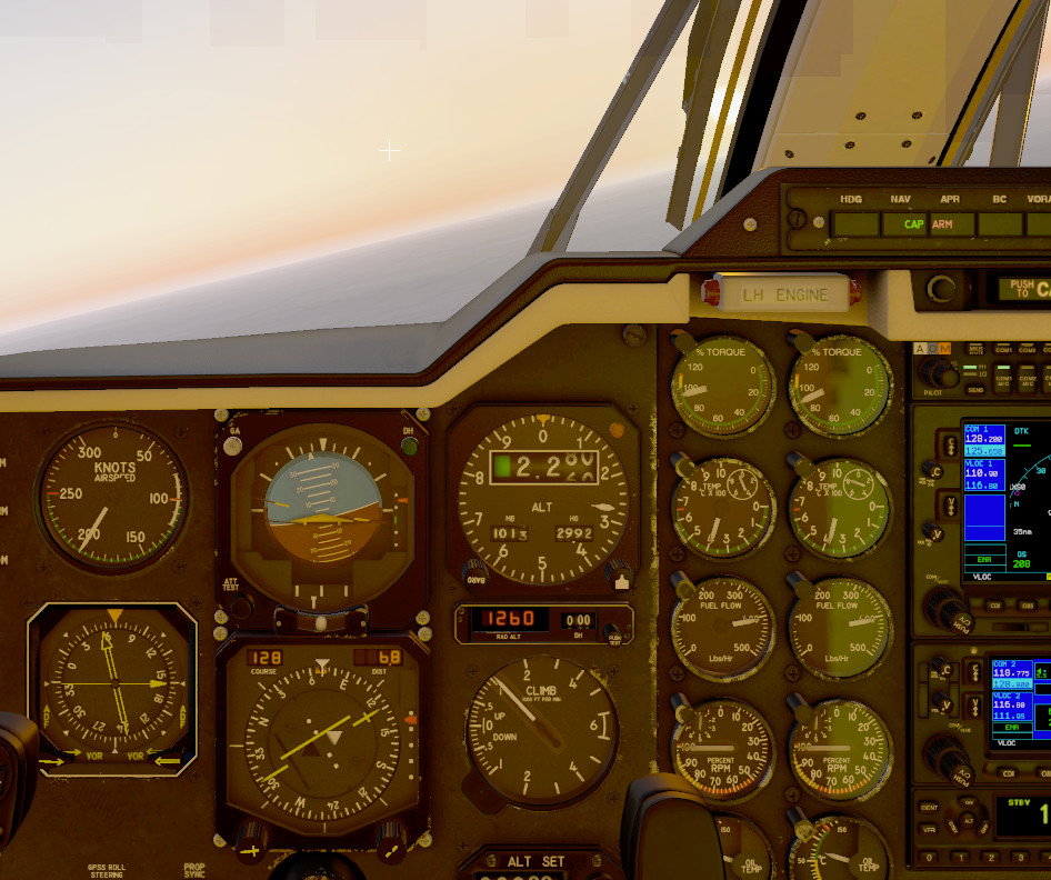
Attitude Indications (ADI)
-
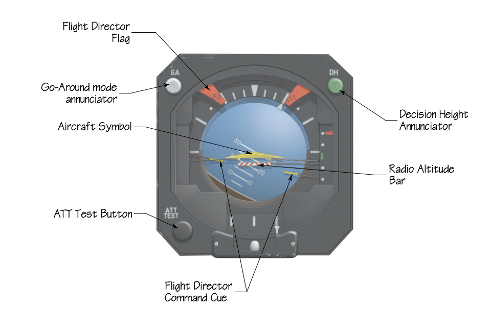
FLIGHT DIRECTOR WARNING FLAG: The FD warning flag appears whenever the FD is unpowered, has failed, or the SBY button is pressed.
-
GO-AROUND MODE ANNUNCIATOR: The go-around annunciator illuminates whenever the Go-Around mode is active. Because Go-Around is an active FD mode, the SBY annunciator will be extinguished in this mode.
-
AIRCRAFT SYMBOL: The aircraft symbol is a stationary symbol that indicates the attitude of the aircraft relative to the both the attitude sphere (roll and pitch) as well as the FD Command Cue Bars. When the aircraft symbol is "flown to" and aligned with the FD command Cue Bar, then the aircraft is following the proper path commanded by the FD per the active FD mode(s) set.
-
FD COMMAND CUE BARS: The FD command cue bars displays the pitch and roll attitudes computed by the FD computer, in order to maintain the desired flight path as set on either the FD MCP or the pitch and roll inputs on the autopilot controller. The cue bars will rise up and down to indicate computed pitch targets and rotate left/right to indicate computed roll targets respectively. The cue bars will be visible whenever any FD mode is active, whether the AP is engaged or not; however, in the case of no FD mode being active, i.e. SBY, then the CUE bars will only visible when the autopilot is engaged and in roll/pitch hold modes. In other words, the cue bars are not visible for basic pitch and roll modes unless the AP servos are engaged.
-
RADIO ALTITUDE BAR: The barber-pole radio altitude bar will appear whenever the absolute altitude above the ground (as sensed by the radar altimeter) is below 200 feet, and a valid ILS signal is being received. The bar will move up towards the aircraft symbol to indicate the decreasing distance between the aircraft and ground and touch the aircraft symbol at touchdown.
-
DECISION HEIGHT ANNUNCIATOR: The decision height (DH) annunciator will illuminate when descending through the altitude set in the Radar Altimeter DH window
-
ATT TEST BUTTON: The ATT test button, when pressed, initiates a self-test. When pressed and operating correctly, the horizon sphere will display a 20º right bank and 10º pitch-up attitude. In addition, the ATT warning flag will be displayed. If the horizon sphere does not indicate the 20º/10º roll & pitch values during the ATT test, the ADI horizon sphere reading should be considered invalid.
Horizontal Situation (HSI) Indications
-
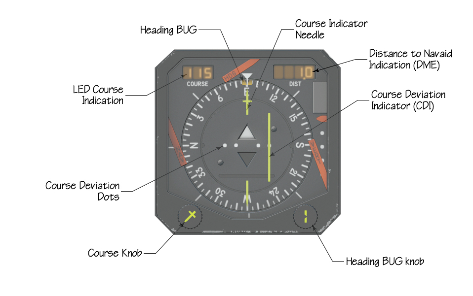
COURSE KNOB: The course knob is used to select a desired magnetic bearing to track, either to/from a VOR radial or ILS localizer course / backcourse. Turning the knob will cause both the LED course indication and Course Indicator Needle to change.
-
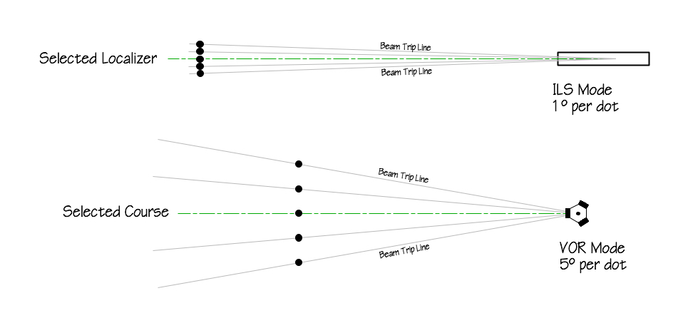
COURSE DEVIATION DOTS: Indicates the deviation, in degrees, from centerline of the selected magnetic course. In VOR mode, each dots represents approx 5º deviation from the selected course. In ILS mode, each dot represents approx 1º deviation from the selected localizer course.
-
LED COURSE INDICATION: The LED course indication is a numerical LED readout of the magnetic bearing selected with the COURSE KNOB.
-
COURSE INDICATOR NEEDLE: The course indicator needle indicates the magnetic bearing selected with the COURSE KNOB and matches the value shown in the LED course indication. The course indicator needle gives a convenient, lateral representation of the desired bearing to track relative to the track of the aircraft.
-
DISTANCE TO NAVAID INDICATION: The distance display will display the distance, in nautical miles, to a tuned-in NAVAID when that navaid contains functioning Distance Measuring Equipment (DME).
-
HEADING BUG / KNOB: The heading bug is adjusted via the Heading knob. The heading bug sets the desired heading to fly when the Flight Director is in HDG mode and the GPSS toggle button is set to HDG. When the aircraft is not aligned with HDG value set, then the FD command cue bars will roll to indicate a turn in the shortest turn direction to achieve the set HDG. If the AP is engaged, then the aircraft will also roll at approximately 30º of bank to follow the FD cue bars. When in HDG mode, the TURN KNOB input is ignored as the TURN KNOB is for roll hold mode, not HDG mode.
-
COURSE DEVIATION INDICATOR: When a valid Navigation signal is received, either VOR, ILS or active GPS flight plan, then the course deviation indicator indicates the deviation amount, in degrees/dot from the selected magnetic course. When a GPS is present and there is a flight plan leg active, then the deviation from the flight plan leg is only indicated on the HSI when the GPS CDI button is set to GPS (and not VLOC). Note that when the GPS is driving the HSIs course deviation indicator, then any course set with the course knob is inconsequential and has no effect.
Encoding Altimeter Indications
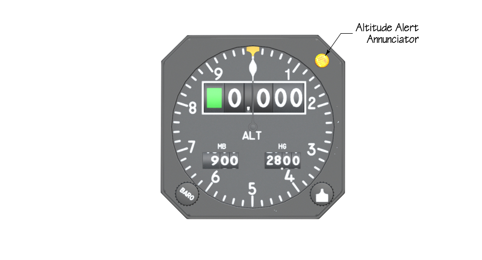
- ALTITUDE ALERT ANNUNCIATOR: The altitude alert annunciator is armed to illuminate whenever the FD is in Altitude Arm mode (ALTSEL). As the current altitude approaches the target altitude preselected (see preselector description below), the altitude alert will illuminate between 250' and 1000' of the target altitude. After altitude capture, the light will also illuminate if the current altitude deviates from the target altitude between 250' and 1000' as long as the preselected altitude is not changed; however, with the autopilot engaged, this is not a likely scenario. Changing the preselected altitude after capture will reset/cancel the Altitude alert annunciator until the next altitude capture event.
Radar Altimeter

- The radar altimeter LED display indicates the height above the terrain, in feet, directly below the aircraft. The LED will come alive whenever the unit has power, the aircraft is airborne, and the terrain below is 2500' or less. The effective range is limited by the transmission power of the radar. The radar altitude is coupled to the decision height circuitry and drives the decision height annunciator on the upper right corner of the ADI (described above)
Autopilot Controller
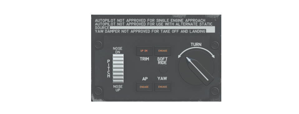
The autopilot (AP) controller is located between the pilot seats. The AP controller is used to:
- Engage the autopilot (Turn knob must be centered)
- Engage the Yaw Damper
- Manually adjust the pitch angle target
- Manually adjust the roll angle target
- Enable SOFT RIDE functionality.
- Determine if the elevator trim surfaces are at their limit and cannot be driven further by the autopilot.
AP ENGAGE: The AP servos are engaged whenever the AP button is pressed and the Turn Knob is centered. When pressed, the AP button will display ENGAGE and the yaw damper will automatically engage also if it is not already engaged, and will also display ENGAGE. When the servos are engaged, the active autopilot mode will be whatever FD mode is selected, if any (SBY light extinguished). If no FD mode is active when the AP is engaged (SBY light illuminated), then the autopilot will default to simple roll hold and pitch hold modes. Pressing the AP button when the servos are already engaged will NOT disengage the AP. Nominal disengagement of the AP is via the red AP disconnect button on the yoke.
YAW DAMPER: The Yaw Damper is engaged by either 1) Pressing the Yaw Damper button or 2) Engaging the AP servos, which will automatically engage the Yaw Damper also. The Yaw Damper may be disengaged at any time by pressing the button
PITCH TRIM WHEEL: The pitch trim wheel is used to manually adjust the AP pitch angle target up or down in proportion to the wheel movement. The wheel movement is continuous and wheel position does not represent any particular pitch angle. The wheel simply adjusts the pitch target up/down. If a FD pitch mode is currently active, such as ALTSET, IAS or VS, then movement of the pitch wheel will cancel the active FD pitch mode and adjust the pitch angle target accordingly.
TURN KNOB: The turn knob is used to manually set the AP roll angle target, up to 30º. There is a detent in the center position and turning the knob out of detent will set the AP target roll angle. If another FD roll (lateral) mode is active, i.e. HDG, NAV or APP, then turning the knob out of detent will cancel the active FD lateral mode. The Turn Knob must be in the center detent position in order to engage another lateral roll mode.
TRIM WARNING: The trim warning annunciator will illuminate whenever the AP is engaged and the elevator trim surfaces are at their limit and cannot be driven by the autopilot any further to trim the aircraft. Illumination of the TRIM annunciator represents an out of trim condition and the autopilot will generally be unable to hold the aircraft pitch targets to maintain the set pitch modes.
SOFT RIDE: The soft ride button adjusts the autopilot constants to be less responsive in rough weather, so the AP is not aggressively trying to compensate for all the disturbances caused by turbulence.
FD Mode Control Panel (MCP)

The FD Mode Control Panel is located on top of the glareshield and is used to select all FD modes, with the exception of the GO-AROUND mode, which is enabled via the GA switch on the left power lever handle. When an FD mode is active, then the related buttons will be illuminated with an annunciator indicating the active FD mode(s). When no FD mode is active, then the SBY annunciator will be illuminated, indicating that the FD is enabled to receive commanded modes. For those modes which feature automatic capture, such as NAV, APR, BC, VORAPP and ALTSEL, the buttons feature split annunciators to indicate whether the active mode is ARMED (for capture) or actively CAPTURED.
- HDG Button:

Pressing the HDG button will activate the FD Heading mode; however, the magnetic heading flown depends on whether the HDG mode is nominal HDG mode or GPSS HDG mode. The following paragraphs explain these concepts further.
For GPS variants of the MU-2, when the HDG button is pressed, either nominal HDG mode or GPSS mode will be activated depending on the state of a GPSS Button found on the panel just to the left of the yoke shaft. We discuss the GPSS concept below and how it affects the HDG mode. For the OEM variant of the MU-2, there is no GPSS mode and only the nominal HDG mode functionality described below applies.
Nominal HDG Operation
When the HDG button is pressed and the nominal HDG mode is active (OEM variant or GPS variants with GPSS set to HDG), then the HDG annunciator will illuminate and the FD will compute a roll angle to turn the aircraft towards the heading bug value set on the HSI. The FD command cue bars will indicate the roll angle computed. If the AP is engaged, the AP will roll the aircraft to align with the FD command cue bars and initiate a turn towards the target heading. Selecting HDG mode will cancel any other active lateral mode (NAV / APPR / BC etc.) Turning the HDG bug knob on the HSI will change the commanded HDG target.
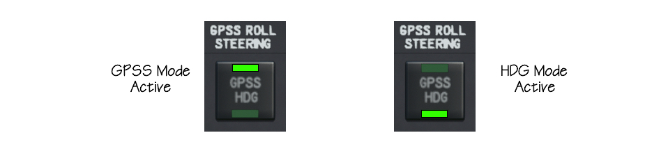
GPSS Operation
The SPZ-500 system was developed before GPS navigation was commonplace and as such, its NAV(igation) mode only tracks terrestrial based radio signals such as VORs / ILS and the FD Computer NAV mode does NOT track GPS flight plans. You can get the autopilot to follow a GPS flight plan; however, using a GPSS (GPS Steering) converter. A GPSS converter is an aftermarket item that is installed to work with older autopilots like the MU2 and allow them to fly a GPS generated flight plan using a clever workaround. The variants of the MU-2 with GPS simulate a GPSS Converter.
The GPS always knows which way it should be heading to follow a flight plan and therefore, the GPS unit can send constantly updating heading targets to the Autopilot. When GPSS mode is active, the autopilot will take its HDG target from the GPS supplied heading values and ignore the HDG value dialed into the HSI heading bug. If there is no active GPS flight plan leg with GPSS active, then the autopilot HDG signal is generally the last HDG value supplied by the GPS. This ensures the aircraft continues heading in the same direction after flying the last leg of a flight plan.
Activating GPSS mode is accomplished by means of a GPSS toggle button on the panel just to the left of the yoke. This button will toggle the desired HDG mode between nominal HDG operation and the GPSS HDG operation. There is a green annunciator on the button to indicate which mode is currently active. When the toggle button indicates GPSS, then the HDG value supplied to the autopilot is coming from the GPS flight plan. When the GPSS toggle button indicates HDG, then the autopilot is following the HDG target dialed into the HSI heading bug.
- NAV (Navigation) Button

The navigation FD mode is used for lateral radio navigation, i.e. VOR and localizer. The SPZ-500 NAV mode is not used for GPS path tracking. VOR navigation mode is selected by pushing the NAV button on the MCP with the NAV 1 receiver tuned to a VOR frequency and the DME distance greater than 20 nautical miles from the station.
If the aircraft is outside the beam trip line when activating NAV VOR mode (see course deviation dots section above), then the FD will automatically activate HDG mode (if not already active) and the NAV button annunciator will illuminate ARM, indicating the system is armed for VOR beam capture. When the aircraft reaches the beam trip line of the selected VOR course, then the FD will automatically switch to the VOR capture (CAP) mode and the HDG and NAV ARM annunciators will extinguish, while the NAV CAP annunciator on the MCP will illuminate, indicating beam capture. After beam capture, but before turning onto the selected course line, the SPZ-500 will maintain the HDG flown at the moment of capture. This HDG value is retained by the system, though turning the HDG knob during VOR CAP mode will not change the aircraft HDG.
If the aircraft is inside the beam trip line when activating NAV VOR mode, the FD will immediately enter NAV CAP mode and begin tracking the beam/selected course. The turn knob must be centered to activate NAV mode.
NAV CAP mode works by tracking the aircraft deviation left or right from the selected course. The system is not aware of any real numbers or course, only deviation from a set course; therefore if you adjust the course while in CAP mode, you will be altering the deviation and the AP will react accordingly to track the new course.
When passing over the station and the VOR signal becomes erratic, a sensor detects station passage and temporarily removes the VOR deviation signal from the command until it is no longer erratic, and maintains HDG; therefore, while over the station, VOR course changes can be made by selecting a new course on the HSI for flying an outbound radial and when the VOR signal stabilizes, the FD will again track the selected course.
NAV ILS mode procedure works the same as NAV VOR described above, with the difference being transparent to the pilot, i.e. the ILS beam is narrower and the AP gains are altered to optimize ILS beam tracking.
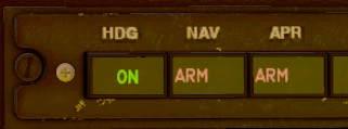
- APR Button

The approach(APR) mode is used to make ILS approaches. APR mode is selected by pressing the APR button when the NAV 1 receiver is tuned to a valid ILS signal. When selected, both the FD localizer (LOC) and glideslope (GS) tracking modes are activated simultaneously. The LOC tracking ARM/CAP status is indicated on the MCP NAV button annunciators as described above, whereas the GS tracking ARM/CAP status is indicated on the APR button annunciators. Note that GS capture is interlocked with the localizer such that the localizer must be CAP(tured) first, before the GS can be CAP(tured). Pitch-modes other than Go-Around (GA), i.e. pitch-hold, IAS or VS may be active when engaging APR mode and those modes will be retained if not in the GS capture range. Depending on the location of the aircraft relative to the LOC and GS beams when APR mode is activated, differing FD modes may be activated and annunciated on the MCP.
If the aircraft it outside a respective LOC/GS beam trip line, then that respective annunciator will indicate ARM. If the aircraft it outside the LOC beam trip line, then the HDG mode will automatically be activated also as described above. The image below shows the FD modes automatically activated when pressing the APR mode button. The aircraft is outside both the LOC and GS beam trip lines and so each mode is ARMED for capture. In addition, the HDG mode is automatically activated.
If the aircraft is inside a respective LOC/GS beam trip line when engaging APR mode, then that respective annunciator will indicate CAP. The image below shows that the aircraft is inside the LOC beam range when engaging APR, but outside the GS beam range; therefore, the LOC mode is CAP(tured) while the GS mode is ARMED until the GS beam is intercepted. Because the APR mode was engaged while inside the LOC beam, the HDG mode was not activated and the plane immediately captured the localizer and begin its turn.
- BC Button

The back course (BC) mode is selected by pushing the BC button on the MCP when NAV 1 is tuned to a valid LOC signal. BC operates the same as the NAV LOC mode described above with regards to ARM/CAP, including automatic activation of HDG mode when activating BC mode outside the LOC beam trip lines; however, the deviation and course signals to the CDI are reversed so as to make the CDI needle display consistent with a normal LOC approach, i.e left needle deflection = localizer beam to the left. GS capture is locked out when in the BC mode.
- VORAPP Button

The VOR approach mode is selected by pushing the VORAPR button on the mode selector with the navigation receiver tuned to a VOR frequency and less than 20 DME miles from the station. This mode operates identically to the NAV VOR mode described above; however, autopilot gains are simply optimized for more precision tracking of the beam to the VOR in this mode. This effect is largely transparent to the pilot.
- ALT Button

Pressing the ALT button will activate the FD Altitude Hold (ALT) mode. When ALT is selected, it will cancel any other pitch mode already active or captured, i.e. the APR-CAP, GA, IAS, VS, ALTSEL or PITCH HOLD modes and the ON annunciator will illuminate. If the Touch Control Steering (TCS) button (see description below) is pressed and held down, then the ALT mode is temporarily disabled and the pilot may maneuver the aircraft to a new altitude without disengaging ALT mode. When the TCS button is released, the new altitude will become the ALT hold reference altitude.
- ALTSEL Button

Pressing the ALTSEL button will activate Altitude Preselect mode. This mode will ARM the FD for altitude capture and the ALTSEL annunciator will indicate ARM. The desired altitude to capture is input via the Altitude Preselect Controller described below. It is recommended that the desired altitude be pre-selected before engaging the ALTSEL mode, or else the aircraft's current altitude may inadvertently be CAP(tured) while adjusting the altitude preselect wheel.
When engaging ALTSEL mode, the aircraft will not automatically alter pitch towards the preselected altitude. The aircraft must be in a pilot-initiated climb or descent towards the preselected altitude in order to CAP(ture) the preselected altitude. Any vertical pitch mode may be initiated by the pilot to maintain a climb or descent towards the preselected altitude, i.e. PITCH-SYNC, VS or IAS modes (see below).
As the aircraft approaches the preselected altitude, the FD will enter a short CAPTURE mode and the ALTSEL annunciator will indicate CAP and the aircraft will begin to level out to the selected altitude. During the CAP(ture) process, all other vertical pitch modes will be cancelled. When the aircraft levels off at the preselected altitude, all ALTSEL annunciators will extinguish and the ALT-hold mode will automatically be engaged and the ALT annunciator will indicate ON as shown above.
- VS Button

Pressing the VS button will activate the Vertical Speed Hold mode and hold the vertical speed value current at the instant the button is pressed. If the vertical speed is rapidly changing when engaging VS mode, then there will be overshoot of the target VS and the AP will take some seconds to return to the target VS. Best practice is to have a stable vertical speed when engaging the mode.
When VS mode is activated, it will cancel any other pitch/capture mode currently active, i.e. APR-CAP, GA, ALT-hold, IAS, or PITCH HOLD. There is no knob or dial to adjust the desired VS with the SPZ-500 variant simulated on the MU-2. Changing the vertical speed with VS mode active can be accomplished in two ways. 1) by adjusting the pitch wheel up or down, which will cancel the VS mode and it must be re-engaged. or 2) Pressing and holding the Touch Control Steering (TCS) button, which will temporarily disable VS mode and the pilot can manually fly the aircraft to another desired vertical speed and release the TCS button to make the new vertical speed the active VS target. The TCS method is the proper method for changing the VS target value with VS mode active.
- IAS Button

Pressing the IAS button will activate the Indicated airspeed Hold (IAS) mode and hold the IAS value current at the instant the button is pressed. If the IAS is rapidly changing when engaging IAS mode, then there will be overshoot of the target airspeed and the AP will take some seconds to return to the target airspeed. Best practice is to have a stable IAS when engaging the mode.
When IAS mode is activated, it will cancel any other pitch/capture mode currently active, i.e. APR-CAP, GA, ALT-hold, VS, or PITCH HOLD. There is no knob or dial to adjust the desired IAS with the SPZ-500 variant simulated on the MU-2. Changing the airspeed with IAS mode active can be accomplished in two ways. 1) by adjusting the pitch wheel up or down, which will cancel the IAS mode and it must be re-engaged. or 2) Pressing and holding the Touch Control Steering (TCS) button, which will temporarily disable IAS mode and the pilot can manually fly the aircraft to another desired airspeed and release the TCS button to make the new airspeed the active IAS target. The TCS method is the proper method for changing the IAS target value with IAS mode active.
- SBY Button

Pressing the SBY button activates the Flight Director's STANDBY MODE (SBY). Engaging SBY mode will cancel/reset all active flight director modes and the flight director command cue will move out of view. When pressed and held, the SBY button also serves as TEST button, causing all the MCP button annunciators to illuminate and simultaneously displays the FD flag on the ADI.
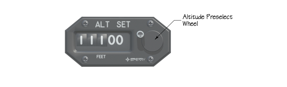
Altitude Alert / Preselect Controller
The Altitude Alert / Preselect controller performs 2 functions:
1) Allows manual entry of a desired target altitude (preselect) for the FD/AP to capture and maintain.
2) Monitors the aircraft altitude and illuminates the Altitude Alert Annunciator under certain criteria.
- ALTITUDE PRESELECT:
The target altitude is selected by turning the altitude preselect wheel until the display indicates the desired target altitude. To capture the target altitude, the FD must be in ALTSEL mode with the ARM annunciator illuminated and the aircraft must be climbing or descending towards the target altitude. Note that the AP will not automatically pitch the aircraft up/down from a level attitude when the ALTSEL mode is activated. The pilot must manually initiate a climb/descent and then set the vertical FD modes as desired, i.e. Pitch hold, IAS or VS modes. When the aircraft approaches the target altitude for capture, a temporary CAPTURE mode becomes active as the aircraft levels off and will cancel all other FD vertical modes. The ALTSEL annunciator will switch from ARM to CAP during the altitude capture process. After the aircraft settles at the target altitude, the CAPTURE mode will cancel and automatically enable the ALT hold mode.
- ALTITUDE ALERTING
As the aircraft gets to within 1000' of the target altitude, the altitude annunciator on the Altimeter will illuminate. The lamp remains illuminated until the aircraft gets to within 250' of the target altitude, at which time the annunciator extinguishes and the alerting system arms to monitor the preselected target altitude. When the system is armed after target altitude capture, the annunciator will illuminate whenever the aircraft altitude deviates by more than 250' from the target altitude. It will also extinguish if the deviation becomes greater than 1000'. Turning the Altitude Preselect Wheel will reset the altitude alerting system.
Touch Control Steering

Touch Control Steering (TCS) is enabled by pressing and holding the black button found on the pilot yokes. TCS is a system designed to allow the pilot to easily change active FD target values like IAS, VS or pitch/roll angle, and do so without disabling the active FD modes or autopilot. This system is used in lieu of a separate panel mounted controller to change the IAS, VS or pitch/roll angle targets. With the AP engaged and a relevant FD mode active, the pilot can press and hold the TCS button, which temporarily disengages the AP and then manually fly the aircraft to a new desired attitude, VS, or IAS. After completing the manual maneuver, the TCS pushbutton is released, and the AP is re-synchronized to the new FD mode values. For example, with IAS mode active, the pilot can push the TCS pushbutton and manually change airspeed by pitching up or down. Once the aircraft is trimmed at the new airspeed, the TCS pushbutton is released and the AP holds the new airspeed (by adjusting pitch trim). If a large pitch attitude change is made, the pilot should normally trim the aircraft before releasing the TCS button.
Go-Around Button
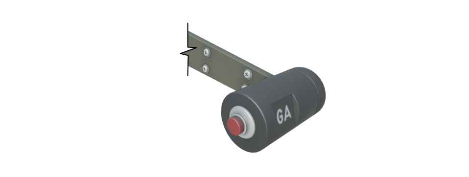
The GO-AROUND (GA) mode is enabled by pressing the remote go-around button on the left side of the left power lever. When enabled, all other FD modes are reset and the remote GA annunciator on the upper left corner of the ADI illuminates. The FD reverts to a wings level (0º) roll target and a 8° nose up pitch target. Selecting GA disconnects the AP servos to facilitate hand flying immediately after GA is enabled. The goal of GA mode is to allow the pilot to rapidly identify and attain a stable climb attitude down the runway for the go-around. Once GA mode is active; however, any FD mode may be selected as desired and the GA mode will be cancelled.