Flight Controls
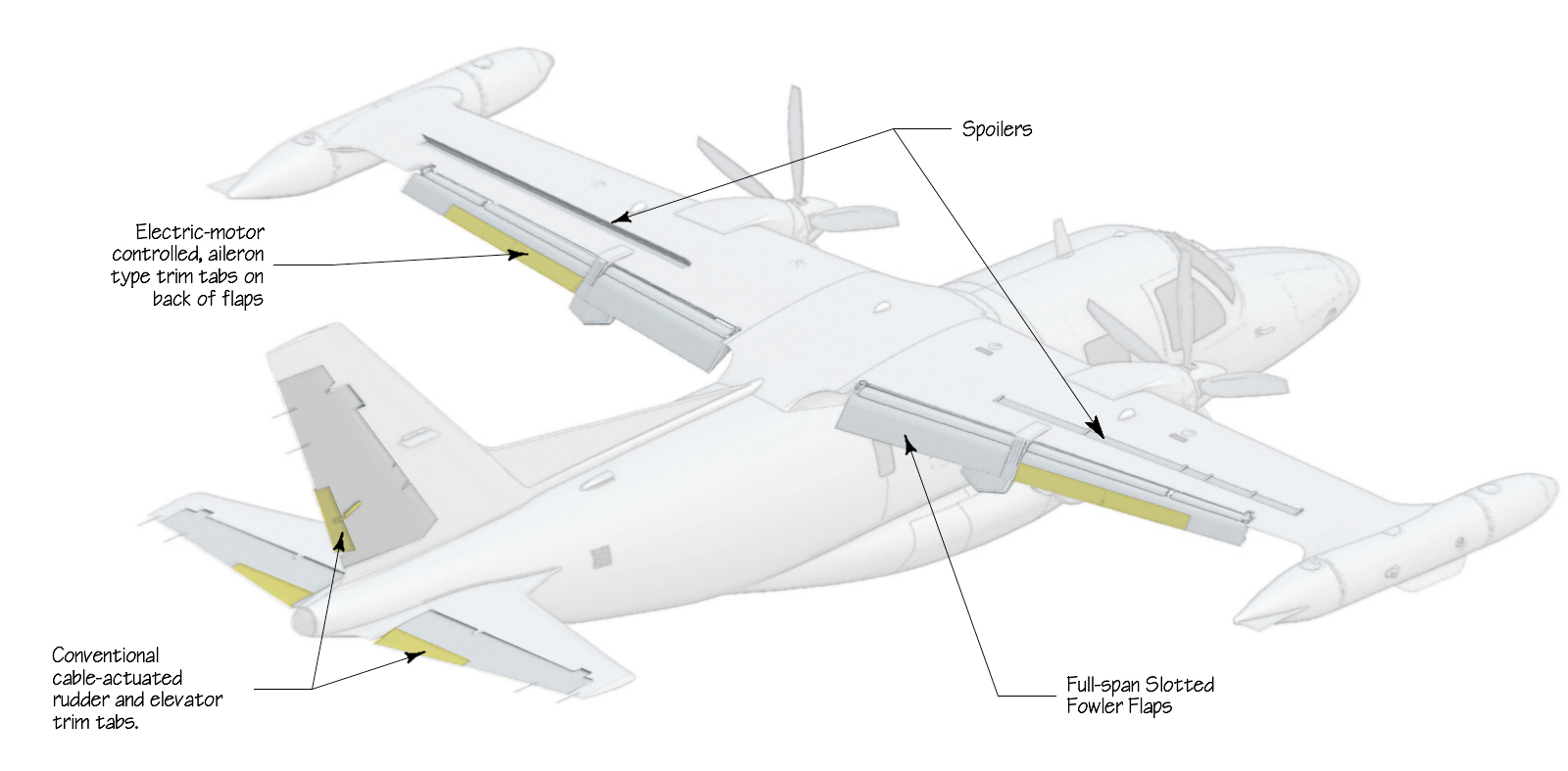
Spoilers
Spoilers are used for lateral control and extend almost full span outboard of the engines. The spoilers are installed on the upper wing surface approximately the full length of the wing. By using spoilers it has been possible to install flaps of unusually large proportions which are effectively full span. Spoilers are cable actuated. Spoi1ers operate differentially through the action of the mixer box. With one spoil er deflected upwards to the maximum of 60° the other will depress 14° below the wing surface.
Wing Flaps
The wing flaps are mechanically interconnected and are actuated by an electric motor. The flap position switch has four positions: UP, 5, 20, and 40 degrees. Placing the switch in any position will cause the flap to move to and stop at the selected position. Placing the switch to UP and will cause the flaps to fully retract. Flap extension times are approximately as follows:
| Transition Range | Time to transition |
|---|---|
| Up to 5 | 17 seconds |
| 5 to 20 | 10 seconds |
| 20 to 40 | 6 seconds |
Flap retraction times are approx as follows:
| Transition Range | Time to transition |
|---|---|
| 40 to 20 | 4 seconds |
| 20 to 5 | 10 seconds |
| 5 to UP | 21 seconds |
The flap position is indicated by four indicator lights: a green light marked UP, and three amber lights marked 5, 20, and 40 respectively.
Trim Tabs
The airplane is equipped with elevator trim tabs, a rudder trim tab and trim ailerons. The elevator and rudder trim tabs are manually operated by tab con- trol wheels located on the lower section of the center pedestal. Trim ailer- ons are controlled by a switch on the center pedestal. Takeoff trim position is shown on the elevator trim indicator by a green line. The mechanical elevator trim position indicator is marked NOSE UP and NOSE DOWN on the respective sides. Amechanical rudder trim position indicator is marked NOSE L and NOSE R. Lateral trim control is established by electrically operated trim ailerons located at the trailing edge of the outer wing flaps. An electrical aileron trim indicator is marked LOWER L WING and LOWER R WING with arrows. If either the right or left electric trim aileron actuator fails, then the working trim aileron may be isolated via the aileron select switch and continue to be operated.
Elevator and Rudder
Each half of the elelevator is supported on two hinges and there is a combined aerodynamic and mass balance near the tip of each elevator. Rudder control is similar to the elevator, with the rudder attachment and balancing similar to one side of the elevator. The two sets of rudder controls each operate a quadrant by push-pull rods. The quadrants are similarly linked. Flexible 5/3211 7 x 19 cables connect to the rudder surface.The two pilot I s control wheel s are joined by chains and sprockets which are linked to a quadrant below the control pedestal. From this point 5/3211 7 x 19 flexible cables run to the mixer box located in the wing center section. Thereafter the control inputs are transferred to the spoilers by a series of push-pull rods and bell cranks. The spoilers are machined from extrusions and there are two on each side of the wing. Each spoiler is attached by dual hinges and is operated by a single rod connection. The actuators have irreversible screwjacks. On the elevator the two trim surfaces are cross 1inked by a chain and sprocket arrangement.The aileron type trim consists of inboard and outboard surfaces located in the inner section of the outboard flaps. Each pair of tabs is mechanically connected and driven by an electric actuator with an irreversible drive mounted in the flap. Trim position is sensed from the actuators.
The left and right electrically connected aileron type trim tabs move in opposite directions to each other. Although operating speeds of the 1eft and right actuators are usually different, accumulation of differences is avoided because the actuator is momentarily stopped through a neutral limit switch.When the guarded TRIM AIL SELECT switch, located on the switch panel, is moved to the LH or RH position, interconnection between left and right tabs is dis- connected and the control surface which has been selected can be operated in- dependently. Trim capability remains even if the control surface on one side becomes inoperative.Double slotted, full span flaps are fitted. They are operated through three actuators per side. The irreversible actuators are driven by an electric motor via gears and torque tubes. It is possible to stop the flaps at the UP, 5°,20° and 40° positions shown by indicator lights located below the selector.The electric motor and gearbox are housed in the wing center section along with the flap limiter controls. The primary actuator and main flap track are approximately in the center of each flap. There are additional smaller actuators and guides at each end. From the motor to the primary actuators, the drive is by torque tUbe; thereafter by flexible shafts to the outboard actuators. The electric motor incorporates an electromagnetic clutch which varies in load carrying capability with current passing through the motor. It will not slip in normal operation.The flap limiter control wil1 stop the flaps at any of the positions shown on the selector quadrant, provided the selector is moved to the particular position. When a position is selected the flap will move to that position and the flap indicator light will illuminate. To slow the rate of flap movement be- tween 0° and 20° an interrupter device is installed which inches the flaps in or out.No emergency means of operating the flaps is provided.